Polarized light is a contrast-enhancing technique that improves the quality of the image obtained with birefringent materials when compared to other techniques such as darkfield and brightfield illumination, differential interference contrast, phase contrast, Hoffman modulation contrast, and fluorescence. Polarized light microscopes have a high degree of sensitivity and can be utilized for both quantitative and qualitative studies targeted at a wide range of anisotropic specimens. Qualitative polarizing microscopy is very popular in practice, with numerous volumes dedicated to the subject. In contrast, the quantitative aspects of polarized light microscopy, which is primarily employed in crystallography, represent a far more difficult subject that is usually restricted to geologists, mineralogists, and chemists. However, steady advances made over the past few years have enabled biologists to study the birefringent character of many anisotropic sub-cellular assemblies.
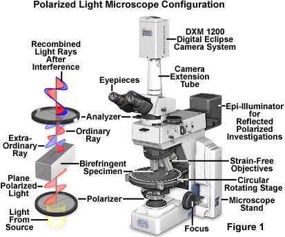
The polarized light microscope is designed to observe and photograph specimens that are visible primarily due to their optically anisotropic character. In order to accomplish this task, the microscope must be equipped with both a polarizer, positioned in the light path somewhere before the specimen, and an analyzer (a second polarizer; see Figure 1), placed in the optical pathway between the objective rear aperture and the observation tubes or camera port. Image contrast arises from the interaction of plane-polarized light with a birefringent (or doubly-refracting) specimen to produce two individual wave components that are each polarized in mutually perpendicular planes. The velocities of these components, which are termed the ordinary and the extraordinary wavefronts (Figure 1), are different and vary with the propagation direction through the specimen. After exiting the specimen, the light components become out of phase, but are recombined with constructive and destructive interference when they pass through the analyzer. These concepts are outlined in Figure 1 for the wavefront field generated by a hypothetical birefringent specimen. In addition, the critical optical and mechanical components of a modern polarized light microscope are illustrated in the figure.
Polarized light microscopy is capable of providing information on absorption color and optical path boundaries between minerals of differing refractive indices, in a manner similar to brightfield illumination, but the technique can also distinguish between isotropic and anisotropic substances. Furthermore, the contrast-enhancing technique exploits the optical properties specific to anisotropy and reveals detailed information concerning the structure and composition of materials that are invaluable for identification and diagnostic purposes.
Isotropic materials, which include a variety of gases, liquids, unstressed glasses and cubic crystals, demonstrate the same optical properties when probed in all directions. These materials have only one refractive index and no restriction on the vibration direction of light passing through them. In contrast, anisotropic materials, which include 90 percent of all solid substances, have optical properties that vary with the orientation of incident light with the crystallographic axes. They demonstrate a range of refractive indices depending both on the propagation direction of light through the substance and on the vibrational plane coordinates. More importantly, anisotropic materials act as beamsplitters and divide light rays into two orthogonal components (as illustrated in Figure 1). The technique of polarizing microscopy exploits the interference of the split light rays, as they are re-united along the same optical path to extract information about anisotropic materials.
Interactive Java Tutorial
Birefringent Crystals in Polarized Light
Explore how birefringent anisotropic crystals interact with polarized light in an optical microscope as the circular stage is rotated through 360 degrees.
Polarized light microscopy is perhaps best known for its applications in the geological sciences, which focus primarily on the study of minerals in rock thin sections. However, a wide variety of other materials can readily be examined in polarized light, including both natural and industrial minerals, cement composites, ceramics, mineral fibers, polymers, starch, wood, urea, and a host of biological macromolecules and structural assemblies. The technique can be used both qualitatively and quantitatively with success, and is an outstanding tool for the materials sciences, geology, chemistry, biology, metallurgy, and even medicine.
Although an understanding of the analytical techniques of polarized microscopy may be perhaps more demanding than other forms of microscopy, it is well worth pursuing, simply for the enhanced information that can be obtained over brightfield imaging. An awareness of the basic principles underlying polarized light microscopy is also essential for the effective interpretation of differential interference contrast (DIC).
Basic Properties of Polarized Light
The wave model of light describes light waves vibrating at right angles to the direction of propagation with all vibration directions being equally probable. This is referred to as "common" or "non-polarized" white light. In plane-polarized light there is only one vibration direction (Figure 1). The human eye-brain system has no sensitivity to the vibration directions of light, and plane-polarized light can only be detected by an intensity or color effect, for example, by reduced glare when wearing polarized sun glasses.
Polarized light is most commonly produced by absorption of light having a set of specific vibration directions in a dichroic medium. Certain natural minerals, such as tourmaline, possess this property, but synthetic films invented by Dr. Edwin H. Land in 1932 soon overtook all other materials as the medium of choice for production of plane-polarized light. Tiny crystallites of iodoquinine sulfate, oriented in the same direction, are embedded in a transparent polymeric film to prevent migration and reorientation of the crystals. Land developed sheets containing polarizing films that were marketed under the trade name of Polaroid®, which has become the accepted generic term for these sheets. Any device capable of selecting plane-polarized light from natural (unpolarized) white light is now referred to as a polar or polarizer, a name first introduced in 1948 by A. F. Hallimond. Today, polarizers are widely used in liquid crystal displays (LCDs), sunglasses, photography, microscopy, and for a myriad of scientific and medical purposes.
There are two polarizing filters in a polarizing microscope - termed the polarizer and analyzer (see Figure 1). The polarizer is positioned beneath the specimen stage usually with its vibration azimuth fixed in the left-to-right, or East-West direction, although most of these elements can be rotated through 360 degrees. The analyzer, usually aligned with a vibration direction oriented North-South, but again rotatable on some microscopes, is placed above the objectives and can be moved in and out of the light path as required. When both the analyzer and polarizer are inserted into the optical path, their vibration azimuths are positioned at right angles to each other. In this configuration, the polarizer and analyzer are said to be crossed, with no light passing through the system and a dark viewfield present in the eyepieces.
For incident light polarized microscopy, the polarizer is positioned in the vertical illuminator and the analyzer is placed above the half mirror. Most rotatable polarizers are graduated to indicate the rotation angle of the transmission azimuth, while analyzers are usually fixed into position (although advanced models can be rotated either 90 or 360 degrees). The polarizer and analyzer are the essential components of the polarizing microscope, but other desirable features include:
- Specialized Stage - A 360-degree circular rotating specimen stage to facilitate orientation studies with centration of the objectives and stage with the microscope optical axis to make the center of rotation coincide with the center of the field of view. Many stages designed for polarized light microscopy also contain a vernier scale so that rotation angle can be measured to an accuracy of 0.1 degree. For advanced studies of conoscopic images, a universal stage having multiple axes of rotation can also be employed to enable observation of the specimen from any direction.
- Strain Free Objectives - Stress introduced into the glass of an objective during assembly can produce spurious optical effects under polarized light, a factor that could compromise performance. Objectives designed for polarized light observation are distinguished from ordinary objectives with the inscription P, PO, or Pol on the barrel. The performance of an objective is limited by several factors, including the anti-reflection coatings used on lens surfaces, and the refractive properties due to angle of incident light on the front lens. In addition, lens strain can be introduced at the cement junction between elements in a lens group or from a single or group of lenses that has been mounted too tightly in the frame.
- Centerable Revolving Nosepiece - Because the objective optical axis position varies from one assembly to another, many polarized light microscopes are equipped with a specialized nosepiece that contains a centering mechanism for individual objectives. This enables each objective to be centered with respect to the stage and microscope optical axis so that specimen features remain in the center of the viewfield when the stage is rotated through 360 degrees.
- Strain Free Condenser - Condensers designed for polarized light microscopy have several features in common, including the use of strain free lenses. Some condensers are equipped with a receptacle for the polarizer or have the polarizing element mounted directly into the condenser, beneath the aperture diaphragm. Many polarized light condensers have a top lens that can be removed (a swing-lens condenser) from the light path to generate nearly parallel illumination wavefronts for low magnification and birefringence observations.
- Eyepieces - Polarized light microscope eyepieces are fitted with a cross wire reticle (or graticule) to mark the center of the field of view. Often, the cross wire reticle is substituted for a photomicrography reticle that assists in focusing the specimen and composing images with a set of frames bounding the area of the viewfield to be captured either digitally or onto film. Orientation of the eyepiece with respect to the polarizer and analyzer is guaranteed by a point pin that slides into the observation tube sleeve.
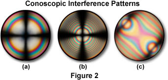
- Bertrand Lens - A specialized lens mounted in an intermediate tube or within the observation tubes, a Bertrand lens projects an interference pattern formed at the objective rear focal plane into focus at the microscope image plane. The lens is designed to enable easy examination of the objective rear focal plane, to allow accurate adjustment of the illuminating aperture diaphragm and to view interference figures, similar to the ones presented in Figure 2. Note that in Figure 2(a) and 2(b), the interference patterns represent those observed with a uniaxial crystal in polarized light, while the pattern in Figure 2(c) is typical of a uniaxial crystal with a first order retardation plate inserted into the optical pathway.
- Compensator and Retardation Plates - Many polarized light microscopes contain a slot to allow the insertion of compensators and/or retardation plates between the crossed polarizers, which are used to enhance optical path differences in the specimen. In most modern microscope designs, this slot is placed either in the microscope nosepiece or an intermediate tube positioned between the body and eyepiece tubes. Compensation plates inserted into the slot are then situated between the specimen and the analyzer.
Polarized light microscopy can be used both with reflected (incident or epi) and transmitted light. Reflected light is useful for the study of opaque materials such as ceramics, mineral oxides and sulfides, metals, alloys, composites, and silicon wafers (see Figure 3). Reflected light techniques require a dedicated set of objectives that have not been corrected for viewing through the cover glass, and those for polarizing work should also be strain free.
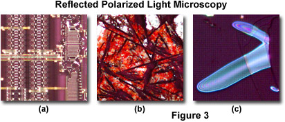
Illustrated in Figure 3 is a series of reflected polarized light photomicrographs of typical specimens imaged utilizing this technique. On the left (Figure 3(a)) is a digital image revealing surface features of a microprocessor integrated circuit. Birefringent elements employed in the fabrication of the circuit are clearly visible in the image, which displays a portion of the chip¡¯s arithmetic logic unit. The blemished surface of a ceramic superconducting crystal (bismuth base) is presented in Figure 3(b), which shows birefringent crystalline areas with interference colors interspersed with grain boundaries. Metallic thin films are also visible with reflected polarized light. Figure 3(c) illustrates blisters that form imperfections in an otherwise confluent thin film of copper (about 0.1 micron thick) sandwiched over a nickel/sodium chloride substrate to form a metallic superlattice assembly.
Careful specimen preparation is essential for good results in polarized light microscopy. The method chosen will depend on the type of material studied. In geological applications, the standard thickness for rock thin sections is 25-30 micrometers. Specimens can be ground down with diamond impregnated wheels and then hand finished to the correct thickness using abrasive powders of successively decreasing grit size. The final specimen should have a cover glass cemented with an optically transparent adhesive. Softer materials can be prepared in a manner similar to biological samples using a microtome. Slices between one and 40 micrometers thick are used for transmitted light observations. These should be strain-free and free from any knife marks. Biological and other soft specimens are mounted between the slide and the cover glass using a mounting medium whose composition will depend on the chemical and physical nature of the specimen. This is particularly significant in the study of synthetic polymers where some media can chemically react with the material being studied and cause degrading structural changes (artifacts).
Manifestations of Polarized Light in Optical Microscopy
Different levels of information can be obtained in plane-polarized light (analyzer removed from the optical path) or with crossed polarizers (analyzer inserted into the optical path). Observations in plane-polarized light reveal details of the optical relief of the specimen, which is manifested in the visibility of boundaries, and increases with refractive index. Differences in the refractive indices of the mounting adhesive and the specimen determine the extent to which light is scattered as it emerges from the uneven specimen surface. Materials with high relief, which appear to stand out from the image, have refractive indices that are appreciably different from the mounting medium. Immersion refractometry is used to measure substances having unknown refractive indices by comparison with oils of known refractive index.
Examinations of transparent or translucent materials in plane-polarized light will be similar to those seen in natural light until the specimen is rotated around the optical axis of the microscope. Then observers may see changes in the brightness and/or the color of the material being examined. This pleochroism (a term used to describe the variation of absorption color with vibration direction of the light) depends on the orientation of the material in the light path and is a characteristic of anisotropic materials only. An example of a material showing pleochroism is crocidolite, more commonly known as blue asbestos. The pleochroic effect helps in the identification of a wide variety of materials.
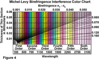
Polarization colors result from the interference of the two components of light split by the anisotropic specimen and may be regarded as white light minus those colors that are interfering destructively. Figure 2 illustrates conoscopic images of uniaxial crystals observed at the objective rear focal plane. Interference patterns are formed by light rays traveling along different axes of the crystal being observed. Uniaxial crystals (Figure 2) display an interference pattern consisting of two intersecting black bars (termed isogyres) that form a Maltese cross-like pattern. When illuminated with white (polarized) light, birefringent specimens produce circular distributions of interference colors (Figure 2), with the inner circles, called isochromes, consisting of increasingly lower order colors (see the Michel-Levy interference color chart, Figure 4). A common center for both the black cross and the isochromes is termed the melatope, which denotes the origin of the light rays traveling along the optical axis of the crystal. Biaxial crystals display two melatopes (not illustrated) and a far more complex pattern of interference rings.
The two orthogonal components of light (ordinary and extraordinary waves) travel at different speeds through the specimen and experience different refractive indices, a phenomena known as birefringence. A quantitative measurement of birefringence is the numerical difference between the wavefront refractive indices. The faster beam emerges first from the specimen with an optical path difference (OPD), which may be regarded as a "winning margin" over the slower one. The analyzer recombines only components of the two beams traveling in the same direction and vibrating in the same plane. The polarizer ensures that the two beams have the same amplitude at the time of recombination for maximum contrast.
Interactive Java Tutorial
Polarizer Rotation and Birefringence
Discover how specimen birefringence is affected by the angle of polarizer when observed in a polarized light microscope.
Constructive and destructive interference of light passing through the analyzer occurs between the orthogonal components, depending on the optical path difference of the specimen and the wavelength of the light, which can be determined from the order of polarization colors. This effect relies on the properties of the specimen, including the thickness difference between the refractive index and the birefringence of the two mutually perpendicular beams, which has a maximum value dependent on the specimen and on the direction of light propagation through the specimen. Optical path differences can be used to extract valuable "tilt" information from the specimen.
Superimposed on the polarization color information is an intensity component. As the specimen is rotated relative to the polarizers, the intensity of the polarization colors varies cyclically, from zero (extinction; Figure 5(d)) up to a maximum brightness at 45 degrees (Figure 5(a), and then back down to zero after a 90-degree rotation. That is why a rotating stage and centration are provided in a polarized light microscope, which are critical elements for determining quantitative aspects of the specimen. Centration of the objective and stage ensures that the center of the stage rotation coincides with the center of the field of view in order to maintain the specimen in the exact center when rotated.
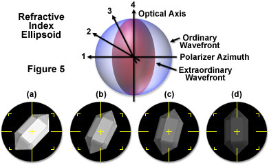
Whenever the specimen is in extinction, the permitted vibration directions of light passing through are parallel with those of either the polarizer or analyzer. This fact can be related to geometrical features of the specimen, such as fiber length, film extrusion direction, and crystal facets. In crossed polarized illumination, isotropic materials can be easily distinguished from anisotropic materials as they remain permanently in extinction (remain dark) when the stage is rotated through 360 degrees.
To assist in the identification of fast and slow wavefronts, or to improve contrast when polarization colors are of low order (such as dark gray), accessory retardation plates or compensators can be inserted in the optical path. These will cause color changes in the specimen, which can be interpreted with the help of a polarization color chart (Michel-Levy chart; see Figure 4). These charts illustrate the polarization colors provided by optical path differences from 0 to 1800-3100 nanometers together with birefringence and thickness values. The wave plate produces its own optical path difference, which is added or subtracted from that of the specimen. When the light passes first through the specimen and then the accessory plate, the optical path differences of the wave plate and the specimen are either added together or subtracted from one another in the way that "winning margins" of two races run in succession are calculated. They are added when the slow vibration directions of the specimen and retardation plate are parallel, and subtracted when the fast vibration direction of the specimen coincides with the slow vibration direction of the accessory plate. If the slow and fast directions are known for the retardation plate (they are usually marked on the mount of commercially available plates), then those of the specimen can be deduced. Since these directions are characteristic for different media, they are well worth determining and are essential for orientation and stress studies.
Applications of Polarized Light Microscopy
The strengths of polarizing microscopy can best be illustrated by examining particular case studies and their associated images. All of the images illustrated in this section were recorded with an Olympus BX51 microscope equipped with polarizing accessories, a research grade instrument designed for analytical investigations. As described above, polarized light microscopy is utilized in a broad range of disciplines, including medicine, biology, geology, materials science, and the food industry. The specimens that are readily examined between crossed polarizers originate from a variety of natural and synthetic sources and include gout crystals, amyloid, muscle tissue, teeth, minerals, solid crystals, liquid crystals, fibers, fats, glasses, ceramics, metals, alloys, among others.
Identification of Gout Crystals
One of the most common medical applications for polarized light microscopy is the identification of gout crystals (monosodium urate) with a first order retardation plate. This practice is so common that many microscope manufacturers offer a gout kit attachment for their laboratory brightfield microscopes that can be purchased by physicians. Gout is an acute, recurrent disease caused by precipitation of urate crystals and characterized by painful inflammation of the joints, primarily in the feet and hands. In practice, several drops of fresh synovial fluid are sandwiched between a microscope slide and cover glass and sealed with nail polish to prevent drying. After the specimen has been prepared, it is examined between crossed polarizers with a first order retardation plate inserted into the optical path.
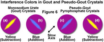
Monosodium urate crystals grow in elongated prisms that have a negative optical sign of birefringence, which generates a yellow (subtraction) interference color when the long axis of the crystal is oriented parallel to the slow axis of the first order retardation plate (Figure 6(a)). Rotating the crystals through 90 degrees changes the interference color to blue (addition color; Figure 6(b)). In contrast, pseudo-gout pyrophosphate crystals, which have similar elongated growth characteristics, exhibit a blue interference color (Figure 6(c)) when oriented parallel to the slow axis of the retardation plate and a yellow color (Figure 6(d)) when perpendicular. The sign of birefringence can be employed to differentiate between gout crystals and those consisting of pyrophosphate. Gout can also be identified with polarized light microscopy in thin sections of human tissue prepared from the extremities. Polarized light is also useful in the medical field to identify amyloid, a protein created by metabolic deficiencies and subsequently deposited in several organs (spleen, liver, kidneys, brain), but not observed in normal tissues.
The strengths of polarizing microscopy can best be illustrated by examining particular case studies and their associated images. All images illustrated in this section were recorded with a Nikon Eclipse E600 microscope equipped with polarizing accessories, a research grade microscope designed for analytical investigations.
Identification of Asbestos Fibers
Asbestos is a generic name for a group of naturally occurring mineral fibers, which have been widely used as insulating materials, brake pads, and to reinforce concrete. These materials can be harmful to the health when inhaled and it is important that their presence in the environment be easily identified. Specimens are commonly screened using scanning electron microscopy and x-ray microanalysis, but polarizing microscopy provides a quicker and easier alternative that can be utilized to distinguish between asbestos and other fibers and between the major types asbestos, including chrysotile, crocidolite, and amosite. From a health care point of view, it is believed that the amphibole asbestos derivatives (crocidolite and amosite) are more harmful than the serpentine, chrysotile.
Plane-polarized light provides information about gross fiber morphology, color, pleochroism, and refractive index. Glass fibers and others that are isotropic will be unaffected by rotation under plane-polarized light while asbestos fibers will display some pleochroism. Chrysotile asbestos fibrils may appear crinkled, like permed or damaged hair, under plane-polarized light, whereas crocidolite and amosite asbestos are straight or slightly curved. Chrysotile has a refractive index of about 1.550, while that of amosite is 1.692, and crocidolite has the highest, with a value of 1.695. Note that the refractive index value of the amphibole asbestos products is much higher than chrysotile.
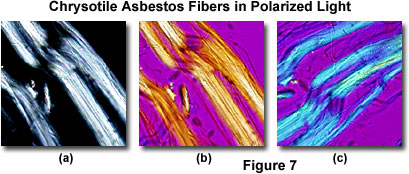
With the use of crossed polarizers it is possible to deduce the permitted vibration direction of the light as it passes through the specimen, and with the first order retardation plate, a determination of the slow and fast vibration directions (Figure 7) can be ascertained. Under crossed polarizers, chrysotile displays pale interference colors, which are basically restricted to low order whites (Figure 7(a)). When a first order retardation plate is added (retardation value of one wavelength, or 530-560 nanometers), the colors of the fiber are transformed. If the fiber is aligned Northwest-Southeast, the retardation plate is additive (white arrow in Figure 7(b)) and produces primarily yellow subtractive interference colors in the fiber. When the fiber is aligned Northeast-Southwest (Figure 7(c)), the plate is additive to produce a higher order blue tint to the fiber with no yellow hues. From this evidence it is possible to deduce that the slow vibration direction of the retardation plate (denoted by the white arrows in Figures 7(b) and 7(c)) is parallel with the long axis of the fiber. Amosite is similar in this respect.
Crocidolite displays blue colors, pleochroism, and murky brown polarization colors. The fast vibration for this fiber is parallel with the long axis. In summary, identification of the three asbestos fiber types depends on shape, refractive indices, pleochroism, birefringence, and fast and slow vibration directions.
Uncovering the History of Rock Formation
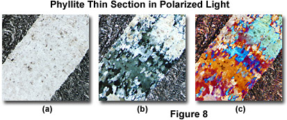
Phyllite - As well as providing information on component minerals, an examination of geological thin sections using polarizing microscopy can reveal a great deal about how the rock was formed. Phyllite, a metamorphic rock, clearly shows the alignment of crystals under the effects of heat and stress. Small-scale folds are visible in the plane-polarized image (Figure 8(a)) and more clearly defined under crossed polarizers (Figure 8(b)) with and without the first order retardation plate. The crossed polarizers image reveals that there are several minerals present, including quartz in gray and whites and micas in higher order colors. The alignment of the micas is clearly apparent. Addition of the first order retardation plate (Figure 8(c)) improves contrast for clear definition in the image.
Oolite - Oolite, a light gray rock composed of siliceous oolites cemented in compact silica, is formed in the sea. The mineral¡¯s name is derived from its structural similarity to fish roe, better known as caviar. Oolite forms in the sea when sand grains are rolled by gentle currents over beds of calcium carbonate or other minerals. These minerals build up around the sand grains and subsequent cementation transforms the grains into coherent rock. The thin sections show the original quartz nuclei (Figure 9(a-c)) on which the buildup of carbonate mineral occurred.
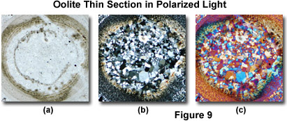
In plane-polarized light (Figure 9(a)), the quartz is virtually invisible having the same refractive index as the cement, while the carbonate mineral, with a different refractive index, shows high contrast. The crossed polarizer image (Figure 9(b)) reveals quartz grains in grays and whites and the calcium carbonate in the characteristic biscuit colored, high order whites. The groups of quartz grains in some of the cores reveal that these are polycrystalline and are metamorphic quartzite particles. When a first order retardation plate is inserted into the optical path (Figure 9(c)), optical path differences become apparent in the specimen, and contrast is enhanced.
Natural and Synthetic Polymers
During the solidification of polymer melts there may be some organization of the polymer chains, a process that is often dependent upon the annealing conditions. When nucleation occurs, the synthetic polymer chains often arrange themselves tangentially and the solidified regions grow radially. These can be seen in crossed polarized illumination as white regions, termed spherulites, with the distinct black extinction crosses. When these spherulites impinge, their boundaries become polygonal. This can be clearly seen in crossed polarizers but not under plane-polarized light.
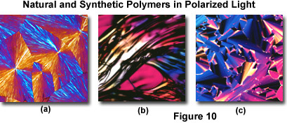
The addition of the first order retardation plate (Figure 10(a)) confirms the tangential arrangement of the polymer chains. The banding occurring in these spherulites indicates slow cooling of the melt allowing the polymer chains to grow out in spirals. This information on thermal history is almost impossible to collect by any other technique. Nucleation in polymer melts can take place as the result of accidental contamination or contact with a nucleating surface and can lead to substantial weakening of the product. Identification of nucleation can be a valuable aid for quality control.
Other polymers may not be birefringent (evidenced by the polycarbonate specimen illustrated in Figure 10(b)), and do not display substantial secondary or tertiary structure. In other cases, both biological and synthetic polymers can undergo a series of lyotropic or thermotropic liquid crystalline phase transitions, which can often be observed and recorded in a polarized light microscope. Figure 10(c) illustrates a birefringent columnar-hexatic liquid crystalline phase exhibited by rod-like DNA molecules at very high aqueous solution concentrations (exceeding 300 milligrams/milliliter).
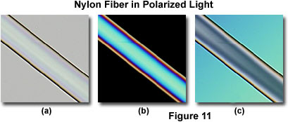
Nylon Fibers - Observations under plane-polarized light (Figure 11(a)) reveal refractive index differences between a nylon fiber and the mounting medium, and the presence of opacifying titanium dioxide particles. The image under crossed polarizers (Figure 11(b)) reveals second and third order polarization colors and their distribution across the fibers indicate that this is a cylindrical and not a lobate fiber useful in predicting mechanical strength. The use of the quartz wedge (Figure 11(c)) enables the determination of optical path differences for birefringence measurements.
In summary, polarizing microscopy provides a vast amount of information about the composition and three-dimensional structure of a variety of samples. Virtually unlimited in its scope, the technique can reveal information about thermal history and the stresses and strains to which a specimen was subjected during formation. Useful in manufacturing and research, polarizing microscopy is a relatively inexpensive and accessible investigative and quality control tool, which can provide information unavailable with any other technique. |


